

Reduced to £5.00 plus £2.50 p&p
Illustrated Glossary - Part 1
Text and CAD Drawings by Kevin West, Project Design Engineer
Following several requests for a layman’s description of some of the terms used in the Project
Progress Reports it has been decided to build up a Glossary for the benefit of members and
volunteers. Descriptions of the parts will use the official LMS terminology. Alongside this glossary
will be a number of articles describing the main features of locomotive construction.
Spring Hanger Brackets
The Driving Wheel Springs on the Patriot class are steel leaf springs, mounted in a buckle,
which is attached to the bottom of the Axlebox. Each end of the top spring leaves are
suspended from the chassis on adjustable Spring Hangers. The attachment at the top of the
Spring Hanger is a casting, the Spring Hanger Bracket, which is riveted to the Main Frames.
Horn Guides
The Horn Guides are castings, normally either of cast iron or steel, that are fitted rigidly to
the Main Frames or Bogie Frames and provide a precision guide for an Axlebox to slide up
and down in. 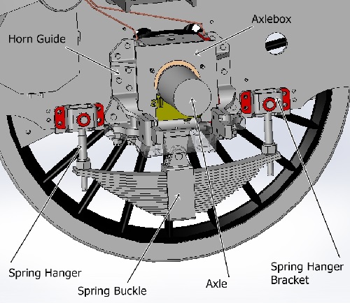
Fitted Bolts
A Fitted Bolt is a fixing used for attaching parts that are not regularly removed from the
finished locomotive. The bolt comprises a head, a plain precision turned diameter body with
a threaded end for fitting a Nut. The parts to be attached will be drilled and the holes then
reamed for a high precision size and finish. The Fitted Bolt is then turned with the body
diameter a few thou (thousands of an inch) larger diameter than the reamed hole to give a
slight interference fit. The bolt is driven into the hole and then a nut is fitted onto the
threaded end.
Stretchers
In very basic terms, a locomotive chassis consists of a pair of plate Main Frames that stand
vertically and run the length of the locomotive, with Buffer Beams at the front and hind
(rear) ends. Between the Frame Plates are fitted Stretchers, to strengthen the structure,
keep the frames aligned and straight and also provide locations and mountings for other
components. These stretchers can be castings, as on the Patriot, although the GWR
fabricated stretchers from plate and angle section steel. This will be covered in more detail in
the next Warrior’s feature on the Locomotive Chassis.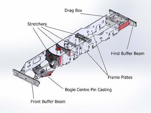
Inside Cylinder
The Patriot class locomotives are fitted with three Cylinders, two outside each Main Frame
Plate and the third, the Inside Cylinder, is fitted between the Frames under the Smoke Box.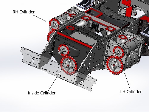
Hind Cylinder Covers
The cylinder bores are sealed at each end with cast iron castings, the Cylinder Covers are
held in place by 20 studs and nuts of 1 inch diameter. The Front Cylinder Cover is normally
fairly plain and is a removable service part. This is to allow the Piston and Piston Rod to be
removed out the front of the Cylinder for servicing. The Cylinder Cover at the hind (LMS
railway terminology for rear) end of the Cylinder is normally not disturbed after initial fitting
as the cover usually also carries the mountings for the Slide Bars. There is also a gland and
steam tight packing for the Piston Rod to pass through.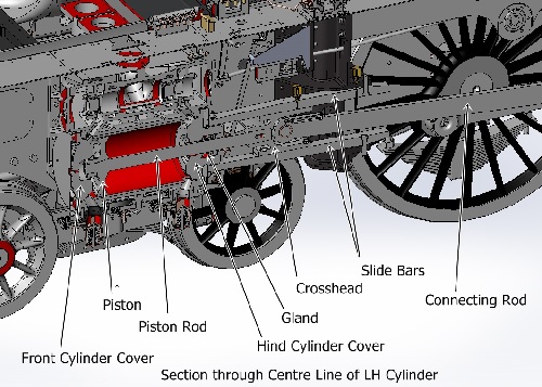
Part 1 of this Glossary was originally published in The Warrior Issue 64.