


Reduced to £5.00 plus £2.50 p&p
Engineering Report - February 2023
Submitted by Kevin West on 24 July, 2023 - 15:28
Work on The Unknown Warrior has continued over the period since the last report. Significant progress is being made on the documentation and project planning to ensure we have captured all the work being done and compiling all the required documentation.
All this effort is taking a large number of hours for the various members of the Engineering Team, with little actual physical progress evident, but without this work 5551 would never pass the certification process to run anywhere.
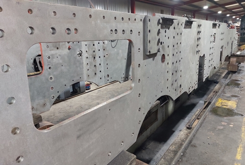
The Chassis of 5551 at West Shed following shot blasting at allow reassembly to re-start.. Photo by Kevin West
Another problem we are seeing more often is the issue of the supply of material to the required specification and the availability of qualified staff to undertake the skilled work required. This is an industry wide problem and has impacted on the delivery of the new Driving Wheels as outlined in the February Monthly Report. It is very frustrating when we get given a delivery date for something and set out the planning around it, only to find out that the actual arrival will be a number of months later.
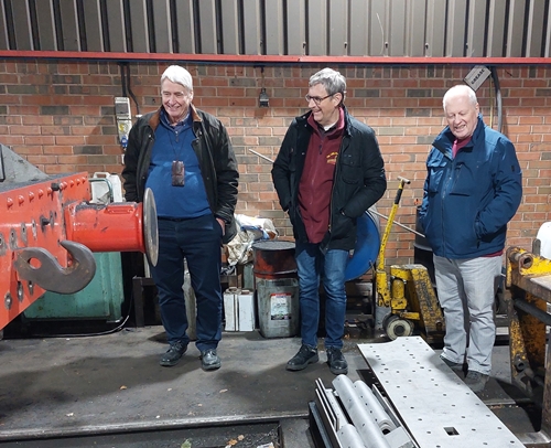
Colin Hall, David Tuffin and Keith Riches discuss future progress. West Shed 29th Jan 2023. Photo by Kevin West
Main Frame Assembly
The Main Frames were finally shot blasted in early January to remove all the paintwork. The Frames are now ready for the welding repairs to be undertaken by a fully qualified welder. This work is expected to take about a week and is planned to have been completed by the time you read this report.
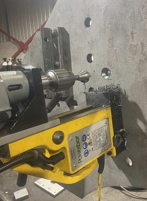
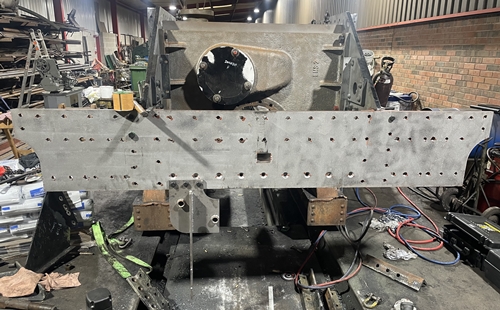
Drilling and countersinking mounting holes for the Front Buffer Beam. Photo by PRCLT
At the front end of the chassis positive progress is being made with the Inside Cylinder placed into the chassis on 2nd February.
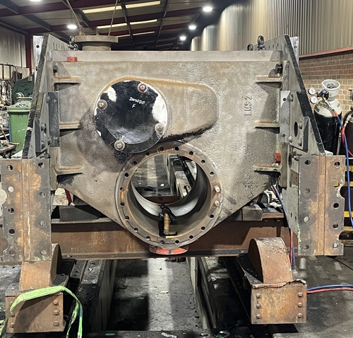
The Inside Cylinder being reinstalled in the chassis – 2nd February 2023. Photo PRCLT
This was followed by the new Front Buffer Beam and associated mounting brackets being fitted.
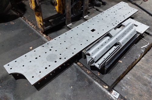
The new Front Buffer Beam and Mounting Brackets. Photo Kevin West
The Front Buffer Beam during assembly to the Chassis. Photo Kevin West
Work away from West Shed continues with all the profiled plates for the new Dragbox having been delivered to Tyseley where the assembly welding will be undertaken by a qualified welder.
The MPI testing of chassis components has been delayed following the decision by the original contractor, who was going to undertake the work, saying they were not now able to do this for us.
We have now identified another contractor and await their costs before an order can be raised.
Design work relating to the mounting of the Air Pump required for the Air Brake system continues. The system being installed on 5551 will closely follow the arrangement used on 6233 Duchess of Sutherland. The Duchess is currently undergoing an extensive period of winter maintenance, including the Driving Wheels being removed for the fitting of new tyres. With the loco striped down it allows access to the inside of the chassis to show what we expect to be fitted to 5551.
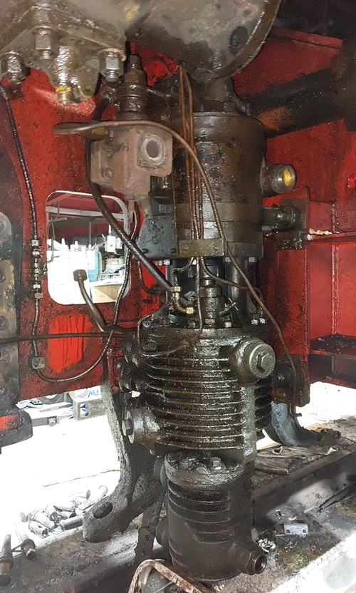
The steam powered Air Pump fitted to 6233. Photo Kevin West
Motion
Machining of motion fittings continues as time allows.
Cylinders
The welding in of the Valve Chest Port Bars on the Outside Cylinders has been completed and fully inspected. The castings have been returned to West Shed where some machining is required on the Port Bars to obtain the correct diameter for the Valve Heads to pass through.
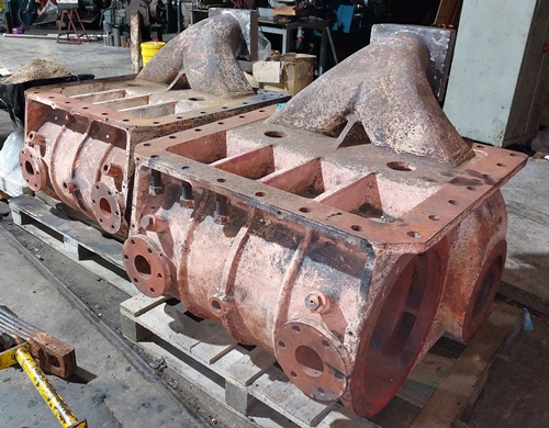
The Outside Cylinders following return to West Shed. Photo by Kevin West
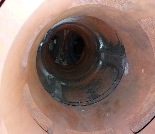
A view into the Valve Chest showing the welded in Port Bars before machining. Photo by Kevin West
Following this machining the Cylinders will be ready to refit onto the chassis.
Driving Wheels
Work continues at William Cook Cast Products on the proof machining of our six Driving Wheels. Two of the castings have been completed and returned to Cook’s plant in Sheffield for inspection and testing. The other four castings will follow as soon as possible. The delay is one example of the lack of skilled personnel to undertake the work.
The replacement Trailing Axle has arrived at West Shed following a protracted journey from South Africa.
Detailed negotiations regarding the assembly of the Driving Wheelsets have continued with the possible contractors. We hope to place the contract as soon as all parts are ready from Cooks.
Bogie
A full design study of the drawings created for the Bogie is underway. Once this has been completed we expect the placing of orders for the patterns and castings required.
Boiler
HBSS continue working on our boiler to an agreed programme which fits within our financial budget and is concentrating on the manufacture and fitting of the Crown Stays.
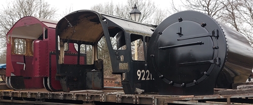
The Cab and Smokebox from 5551 alongside the Cab from 9F 92212. Photo by Kevin West
Tender
A similar planned schedule of work applies at Leaky Finders for the Tender Chassis. All work on the Chassis plate work assembly is finished.
The current focus of activity are the Tender Wheelsets which are being subjected to a number of NDT tests on the wheel castings and the axles. These tests are required to ensure the parts are sound and acceptable for use with 5551.
Tender Tank Design
This has been the area subjected to the most design effort over the last few weeks. At the projects’ Board Meeting at the end of November a number of questions were raised in relation to the progress on the design of the Tender Tank, primarily relating to the water capacity and appearance. Our Chief Engineer was tasked to provide an update at the January Board Meeting.
The aims of the project have been to recreate the classic look of a Patriot class locomotive, with the LMS group standard low sided Fowler tender. The design of this tender originated on the Midland Railway in the early 1900s. There were minor changes up to the early 1930s when the Patriots were built, but to all intent and purpose were mainly the old Midland design.
The low sided tenders carried a water capacity of 3,500 gallons in the main tank and a well tank that runs between the Inner Frames of the chassis. Coal capacity was 5 tons, although this was increased to 5½ tons when fitted with coal rails above the sides. The tender tanks included a narrow body which were 7’ 1” wide, narrower than the 7’ 10” width of the locomotive cab. The original 45551 was one of two Patriots fitted with a high straight-sided version of this tender for several years in the late 1950s and early 60s. There were only 10 of this type of tender built and they were originally paired with the Jubilee class locos. Water capacity was the same 3,500 gallons, but they carried 7 tons of coal.
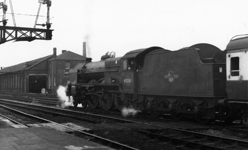
45551 fitted with High Straight Sided Tender at Hereford 16th July 1960. Photo by LMS Patriot Project
Looking to the future of 5551 operating on the national network the biggest consideration is water capacity. We must be able to run for 80 miles between water stops with sufficient spare water capacity to not run dry if held in a significant delay anywhere on our route. For this we plan to have 1,000 gallons in the tank in reserve. The original tank capacity then gave just 2,500 gallons to consume between fills. This is not considered enough, so a redesign of the tank to increase water capacity as much as practical, while keeping the outward appearance as close to the original design was started. We also have to take into consideration other elements and systems such as the Air Braking system and the safety and signalling systems that we need to fit onto 5551 that were never fitted to the original locomotives.
So, how can we squeeze more water into something that looks the same? The original tenders were fitted with water pick up scoops to collect water from troughs between the track whilst on the move. Removing this equipment saves a little weight and gives a little more water capacity in place of the original delivery tube that ran through to the top of the tank.
We are also looking at reconfiguring the coal space to help the coal to self-trim down to the shovelling plate as much as possible. To explain this a little more the original design has the coal space sloping down from the top of the water tank for about half of the length of the coal space. The rear section of the coal space had a level section over the top of the tank where the coal would just sit until the fireman climbed into the tender to pull it forward with the rake. This is no longer permitted while working out on the main line where there could possibly be an overhead line carrying 25KvA. By continuing the slope of the coal space right to the rear coal space bulkhead we think the coal will work forward by itself. The wedge shaped space on top of the main water tank plus the space formally occupied by the water scoop dome is now taken by a supplementary top water tank. This top tank will be filled by connecting hoses to the low level fillers located between the rear and trailing wheelsets. Once this tank is full, internal overspill pipes will flow into the main tank below. This ensures the top tank will always be filled first. There will be standard filler points on the top of both the main and top tanks, although these will not be used whilst running under the wires.
For the same reasons we are not duplicating the original storage points for the long firing irons and rakes which were carried in racks above the coal space. An internal firing iron tunnel is located along the fireman’s side of the coal space. At the front of the coal space on the driver’s side there will be a vertical enclosure to house the electronics relating to the safety and braking systems we have to fit to run on the national network.
Having completed the modifications detailed above it was realised that by widening the tender body to match the cab it would bring the water capacity up to almost 4,200 gallons, giving us slightly more than carried by Black 5s and Jubilees running out on the main line which have 4,000 gallon capacity tenders.
There then came the question of where we can fit three large air tanks that are required for the Air Brake system. On the Duchess these are mounted onto a sub-structure which is hung off the tender frames below the water tank, this is flat bottomed, without the well we have between the inner frames of the chassis. First thoughts were we would have to sacrifice some of the well to mount these tanks, but after a little work and some checks regarding the movement of the Brake Gear it has been found the tanks can be mounted on a sub-raft structure that hangs from the tender chassis. The tanks will be below the well so we do not lose any valuable water space.
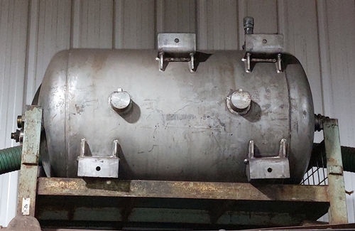
Air Tank to be fitted under the tender of 5551. Photo by Kevin West
These changes are necessary to give 5551 any chance of running out on the main line so I hope you understand why we have to include them in our design.
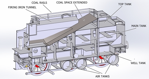
Sectional View of the proposed Tender for 5551. Photo by Kevin West. LMS Patriot Project
I hope the cad image opposite gives a clear understanding of the proposals.