

Reduced to £5.00 plus £2.50 p&p
Engineering Update - October 2020
Submitted by Kevin West on 23 April, 2021 - 19:57
Work on The Unknown Warrior has continued at a limited pace since the last report due to the effects of the current world situation.
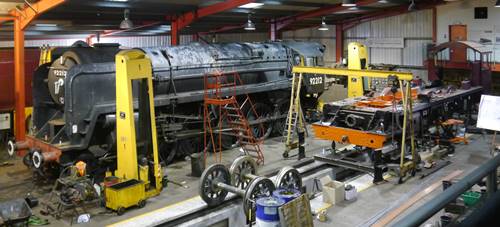
5551 shares the workshop with new arrival Class 9F 92212. Photo by PRCLT
The PRCLT trust engineers and the majority of our suppliers have now returned to work and good progress is being made on the locomotive build. However, this report is being written on the first day of the new lockdown, so we will have to see what effect it has on progress over the next month, at least!
We are trying to make as much useful progress as we can in these different times, so some of our approaches are slightly off from the old normal. All of this boils down to one thing, the continued financial support of you, our members. Without your donations we are unable to plan the still considerable expenditure required to complete 5551.
Chassis & Motion
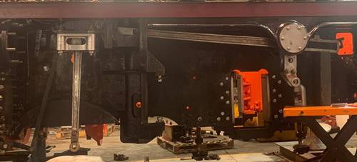
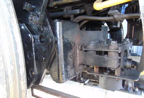
The PRCLT staff have continued work on the locomotive chassis at West Shed, particularly on the Lubrication system with manufacture of Pipe Clips and some adjustment of the pipework already installed in the light of their considerable experience of running 6233.
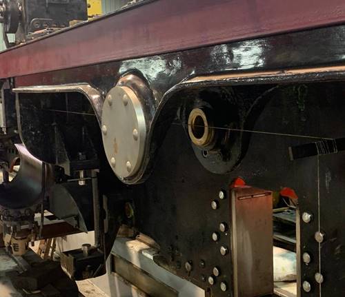
RH Leading Axlebox Guides showing the Lubrication pipework in position. Photo by Andy Collinson.
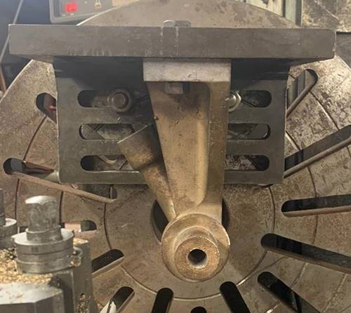
Another area receiving attention is the motion set up. The Frames have been measured to allow fitting of alignment buttons each side of the Horn Guide openings. These will aid correct alignment of the axleboxes on future repairs and maintenance.
On the LH side engine a string line for the Valve Rod centre was set up to check alignment.
xxx. Photo by PRCLT
xxx. Photo by PRCLT
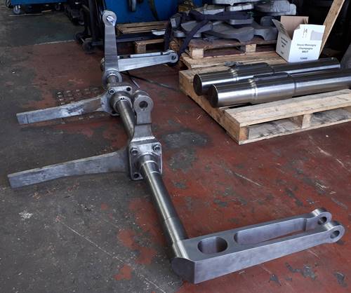
Once this had been completed the Radius Rod and Combination Levers have been trial mounted to check alignment and clearances. A few minor adjustments have been found that will be addressed in the coming months.
The Radius Rod and Combination Lever mounted for clearance checks. Photo by PRCLT
LH Combination Lever. Photo by Andy Collinson
The outside Expansion Link bushes have been measured up to establish where the excessive side play had come from. Corrective work is underway to bring back to the correct tolerances and clearances. Similar work on the RH engine is required to follow.
The LH Expansion Link undergoing checking. Photo by Andy Collinson
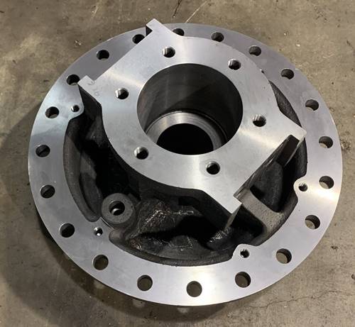
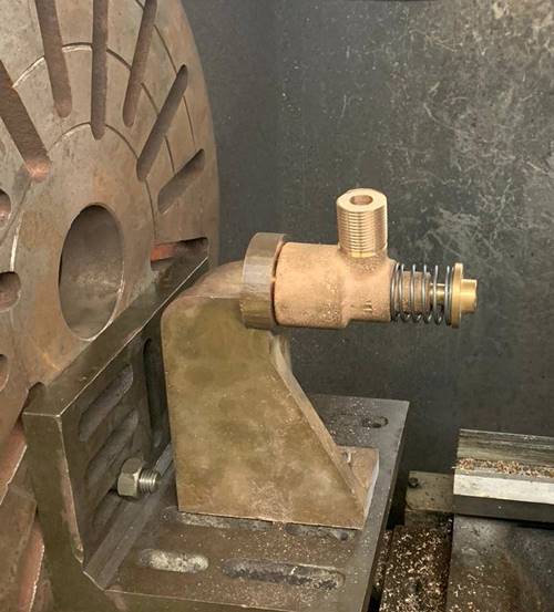
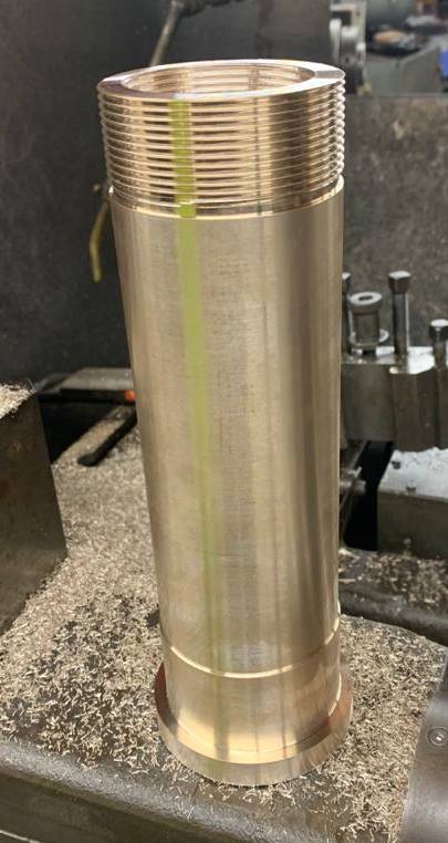
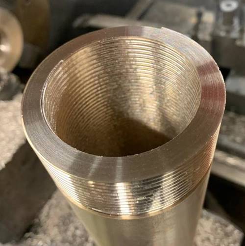
The Rear Valve Chest Covers have had the threads tapped for the Oil Fittings.
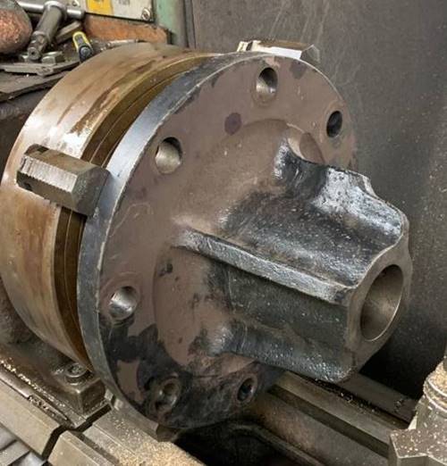
A Valve Chest Cover mounted in the lathe for some minor machining. Photo by PRCLT
The machining of the Valve Rod Crossheads castings has started.
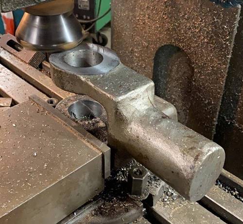
Machining of the Valve Rod Crossheads has started. Photo by PRCLT
The LH Valve Rod Crosshead Guide. Photo by PRCLT
The replacement Rear Cylinder Covers have been machined and delivered to West Shed.
A Rear Cylinder Cover following delivery to West Shed. Photo by Andy Collinson
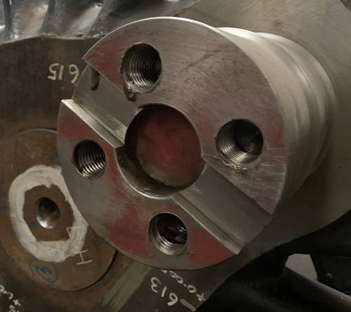
The Reverser Shafts have been delivered to West Shed. We believe the Main Reverser Shaft design and manufacture will need a little work to obtain the required approvals for the assembly as this was agreed with our previous approvals body. We now have to obtain approval by Ricardo Rail.
The Reverser Shaft. Photo by Kevin West
Driving Wheels
Following the successful work on the Crank Pins reported last issue, are now progressing correction of the welded repair to 3 of the wheels.
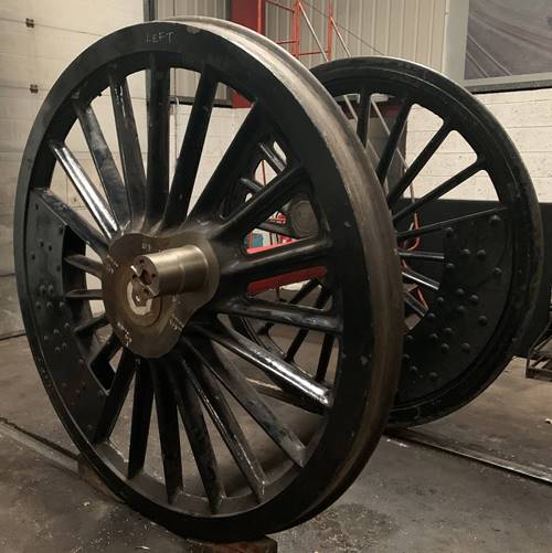
The Centre Driving Wheelset following delivery to West Shed. Photo by Andy Collinson
The new Crank Pins in close up. Photo by Andy Collinson
As described in my last report this relates to three of the driving wheels where a contractor miss-read the drawing and machined a keyway in the wrong position.
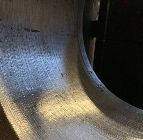
A view on the inside of the Centre Driving Wheel. This shows the Crank Pin at top left with the retaining ring formed over to lock it into the wheel. The axle is to the bottom right, covered in grease to protect the journal. At the joint between the Axle and Wheel can be seen the keyway, correctly positioned in line between the centre of the Axle and Crank Pin. This feature is the keyway incorrectly machined on 3 of the wheels. Photo by Andy Collinson
An agreed repair method was put in place and undertaken before the wheelsets were assembled. The repair method included preparation, welding and inspection stages to ensure an acceptable outcome. As part of the work now being undertaken to obtain full approval we were asked to provide the covering welding and inspection paperwork. Unfortunately, this paperwork could not be found in the Project’s archive. Enquiry’s to the company that did the weld repair produced some paperwork, which only clouded the issue rather than solved it. They believed that more paperwork was available, but it was not accessible due to the admin staff being on furlough during the first lockdown.
We therefore had an inspection of the weld on one wheel undertaken by an independent welding inspector, which indicated that there were possible issues with the weld. In the light of these issues the only way we would obtain approval was to have the 3 wheels pressed off their axles, the old weld removed and reapplied to an approved method with all the required inspections and paperwork in place. The three wheels involved are both wheels on the centre driving axle and the Left Hand wheel on the Trailing axle. All three wheelsets have been transported to Ian Riley’s works in Heyford, where both wheels from the centre wheelset have been removed from the axle and prepared for removal of the old weld. This has confirmed the findings of the inspection with areas of void in the welding. This is an area of weakness which could have in the worst case resulted in cracking and possible failure in service. A full inspection undertaken when the work was originally done should have shown up these voids and makes us wonder if this was ever inspected when originally done?
A view into the bore of one of the wheels following removal from the axle. One of the voids in the original weld can be seen at 9 o’clock. Photo by Ian Riley & Sons
Once all the original weld has been removed the casting will be prepared to be built up with new weld following an approved procedure and inspection process before boring to the correct size for pressing back onto the axle. The processes for undertaking this work is in the final stages of being agreed between the contractors and Ricardo Rail.
The left hand trailing wheel is causing a problem at present, as so far all efforts to remove the wheel from the axle have failed. We are worried about increasing the pressure much more in case it causes damage to the wheel casting itself. We don’t want to end up with a damaged wheel casting that needs to be replaced! At present we are looking at various options to rectify this wheel, which may mean we have to replace the axle. This again is a worst case, but much cheaper than having to replace the wheel and tyre.
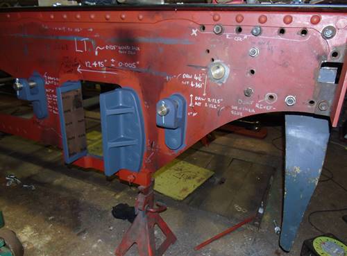
Bogie
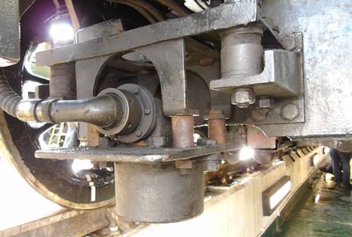
Further to the investigation work mentioned in the last report, it has been decided that the bogie must be reworked to reflect the original design as closely as possible. The bogie we have at present is to a hybrid design to use the original class 8F axleboxes acquired along with the wheelset from ex Barry locomotive No. 48518. These axleboxes are 11” wide against the original Patriot boxes which are only 10”. Between each Axlebox is an Equalising Spring Beam which has its centre bearing onto the underside of the Bogie Centre casting. The spring itself is suspended from the Equalising Beams. The ends of the Beam bear on the top centre of the axleboxes. It has to bear on the middle of the width of the axlebox to spread the load equally. With the wider axlebox from the 8F the centres of the springs are closer together than on the original Patriot design. It follows that the Bogie Frame have to be closer to clear the Equalising Beam, so we ended up with a narrower Bogie Frame than the original design.
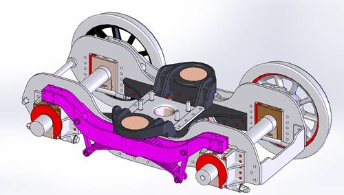
A CAD image of the Bogie. For clarity the 2 wheels this side have been removed and the Equalising Beam is shown in purple. Image by Kevin West
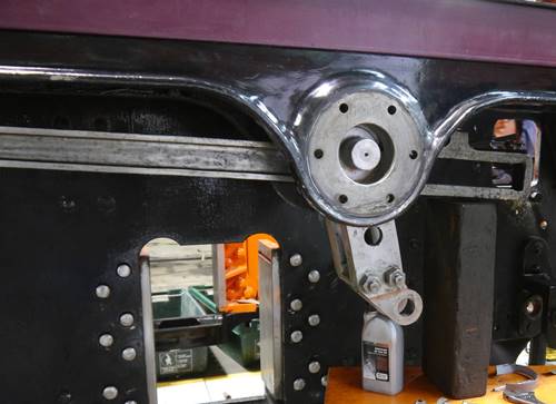
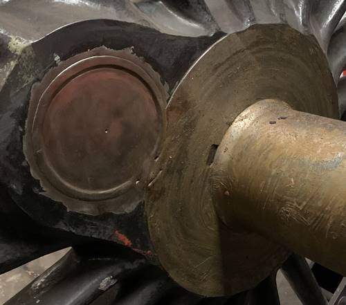
When we move up through the bogie towards the locomotive chassis we have the dome shaped Pindle’s attached to the locomotive Frame assembly. The Pindles sit in a Cup that floats on a bronze bearing pad on the top of the Bogie Centre casting. This gives a direct load bearing line from the Bogie Wheels, through the axlebox, Equalising Beam, Bogie Centre casting, Pindle Cup, Pindle into the Locomotive chassis. I hope the following cut away CAD images will show what I have tried to describe above.
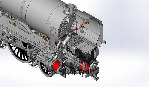
A CAD image of the front end of the locomotive. It shows where the cuts have been made, through the Bogie centre on the left and through the Leading Axle on the right. Image by Kevin West
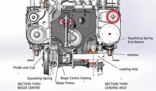
A CAD image section view. The vertical dashed lines indicate the load paths up through the bogie into the locomotive chassis. Image by Kevin West
By using the wider 8F axleboxes it reduces the distance between the Equalising Beams and the load paths shown on the section view above and possibly has an effect on the stability of the front end of the locomotive. To have this change in design accepted we have to prove that there is no effect on the way the locomotive rides when out on the track. It could be possible to undertake this work, but we have nobody in the project with the required technical skills to undertake this work. We could even go through all the work only to have the change rejected by the approval authorities. By returning to the original design we only have to show we have built to the original design. This is the route we have decided to take.
The hybrid design had been discussed with the approval authority we had back at the time it was assembled and they had given the go ahead, but once again we cannot find any documentation relating to these discussions.
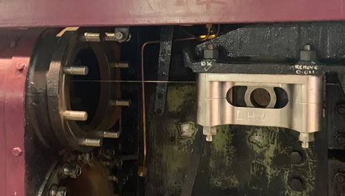
One design change we will be submitting is to replace the original bar front stretcher with a plate stretcher similar to that fitted to 46100 Royal Scot to mount the AWS gear in the 1950’s. Through our friends at Locomotive Services, Crewe, we have examined, photographed and measured up 6100’s bogie ready for drawing preparation. The CAD image of the Bogie above shows this projected change.
The front right corner of 6100’s bogie showing the replaced stretcher to mount the AWS gear. The original shape of the frame plate can be seen, we will possible square off the bottom corner to provide another mounting point for the stretcher. Photo by Kevin West
A view from underneath of the AWS gear on 6100. Photo by Kevin West
Front view of the AWS gear on 6100. Photo by Kevin West
Lubrication System
The lubrication system is being assessed by the PRCLT engineers as part of the work being undertaken on the chassis.
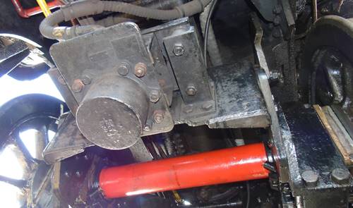
Back in the early days of the project two mechanical lubricators, one 16 feed and an 8 feed, were obtained for use on 5551, but they are not the correct type as fitted to the original locomotives. The original fit was a 12 feed lubricator both sides, the left side suppling oil to the cylinders and the right to the driving axleboxes and the inside motion. By chance the Jubilees class were fitted with a 16 feed lubricator on the left for its cylinders and an 8 feed on the right for the axleboxes, so that is what we have at present.
We have recently been made aware of an issue with the 16 feed unit installed on 5551. It does not have an oil warmer coil to warm up the thick cylinder oil in the winter months to aid the essential lubrication of the cylinders. At present we have been offered the loan of a correct 12 feed Lubricator from 46203 Princess Margret Rose, although we will have to replace this in the near future. We are investigating the production of a small batch to sell on to other loco owners to help recover some of the costs.
Some modification of the pipework around the lubricator will be required to achieve the changeover.
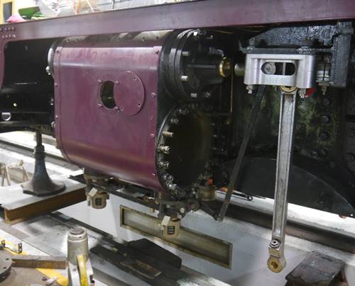
The Cylinder Lubricator from 42603 temporarily mounted on 5551 to enable pipe runs to be modified. The heating coil connections can be seen low down on the end face. Photo by Kevin West
Fittings
Simon Scott has been busy turning very expensive bronze round and hexagon bar into fittings and bushes for the lubrication system and Valve Rod Bushes.
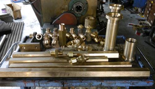
A selection of fittings and bushes after machining. Photo by Andy Collinson
Completed so far are the Drain Cocks, from castings supplied previously and the Adaptors to mount the Drain Cocks to the Cylinder Relief Valves.
The pipework requires numerous fittings and adaptors to join the pipes to the Lubricators or into the part being lubricated. Pipe Nipples are silver soldered to the copper pipe and held in place with a Pipe Nut. Where a long pipe run requires a joint one side of the joint will have a Pipe Adaptor silver soldered on with a Pipe Nipple and Nut on the other side to make a screwed connection. To add to the work, the systems use a variety of pipe sizes, the most common being 3/8” & ½” diameter. Each pipe size has its own size of fittings.
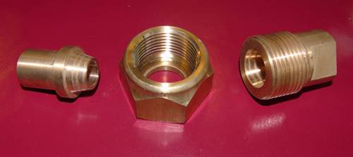
A Pipe Nipple, Pipe Nut and Pipe Adaptor. Photo by Kevin West
Simon has also been machining the Cylinder Valve Chest Drain Cock Mountings, for both the Inside and Outside cylinders. These castings have been to hand for a while but not machined due to being awkward to set up and machine.
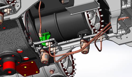
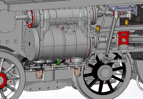
CAD image of the underside of the Inside Cylinder showing the Drain Cocks and Operating Gear. The Inside Valve Chest Mounting is shown in green. Image by Kevin West
The Inside Valve Chest Drain Cock Mounting casting set up on the lathe to machine the thread that the Drain Cock screws onto. Photo by PRCLT
The thread has been cut and a Drain Cock screwed on to check the fit. Photo by PRCLT
The Outside Valve Chest Drain Cock Mounting castings are handed for LH and RH cylinders. These are screwed into a threaded hole in the bottom of the Cylinder castings.
CAD image of the LH Outside Cylinder showing the Drain Cocks and Operating Gear. The Valve Chest Mounting is shown in green. Image by Kevin West
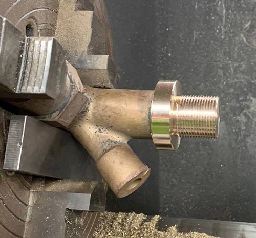
The LH Outside Valve Chest Drain Cock Mounting casting set up on the lathe to machine the thread that screws into the cylinder. Photo by PRCLT
Other parts recently manufactured recently include the Valve Rod Bushes and Nuts and the Oil Adaptors. The Oil Adaptors screw into the Rear Valve Chest Covers and have a long tail which delivers the oil right down to the rod inside the Valve Rod Bush.
A Valve Rod Oil Adaptor showing the long delivery tail. Photo by PRCLT
The Valve Rod Bushes fit into the Rear Valve Chest Covers and are retained by a round castellated nut on the outer end. The bore is serrated to provide a key for white metal that is used as a bearing surface.
One of the Valve Rod Bushes following machining. Photo by PRCLT
Close up view showing the internal serrations for the white metal. Photo by PRCLT
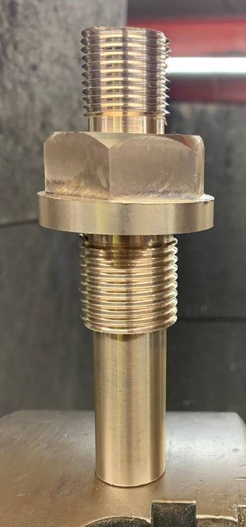
View showing the Rear Valve Chest Cover in position with the Valve Rod Bush, Nut and Oil Adaptor in place. Photo by PRCLT
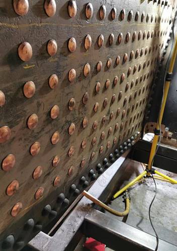
Boiler
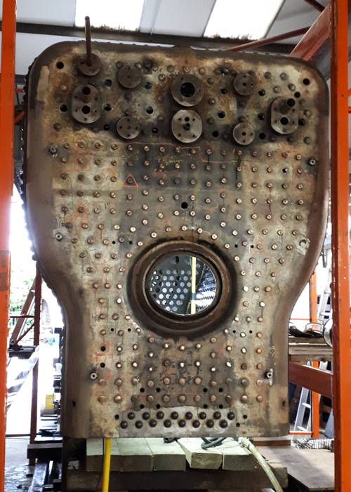
Boiler Backhead in the workshop at HBSS. Photo by Kevin West
Work has been progressing on securing the stays into the Firebox before the Boiler moves from HBSS to West Shed for storage. HBSS will also fit the Boiler Slides before the move to enable the Boiler to be dropped into the frames if the situation allows. We had planned slow down on work at HBSS as it is not worth having a finished boiler without a chassis to fit it into.
The Inner Firebox with the stays formed down. Photo by HBSS
This suited HBSS as well as they have a number of other boilers to work on. Our boiler was taking up workshop space that this other work could utilise. HBSS are expecting another boiler delivery towards the end of November and we are expecting to use the same transporter to move our boiler south instead of an empty journey.
Tender
Leaky Finders are almost finished work on the Chassis structure, with only a limited amount of riveting required at the rear end before the Rear Buffer Beam can be fitted.
LH rear end of the Tender chassis showing the Horn Guides and Spring Hanger Brackets in place.. Photo by Kevin West
All the Horn Guides and Spring Mounting Brackets are fitted and the Brake Gear has been trialed fitted.
View from inside the Tender chassis showing the Brake Gear trial fitted. Photo by Kevin West
Work is continuing only when Leaky Finders are not employed at the West Somerset or Bodmin & Wenford Railway.
Paperwork
Work continues on trying to locate paperwork.
Main Line Running Gear
Work continues on various elements of the provision of the main line running gear.
Tender Tank Design
No progress since last report.