Engineering Update - November 2019
Work on The Unknown Warrior has continued at various location since the last report.
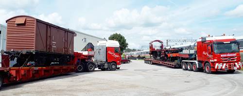
The two road transporter loaded up ready to depart from Crewe Heritage Centre, 12th August 2019. Photo – Kevin West
Chassis
Move to Princess Royal Class Locomotive Trust, West Shed, Midland Railway Centre.
Following the decision to award the contract to complete The Unknown Warrior to the Princess Royal Class Locomotive Trust, based at the West Shed at the Midland Railway Centre, we had to make arrangements to move the locomotive from Crewe.
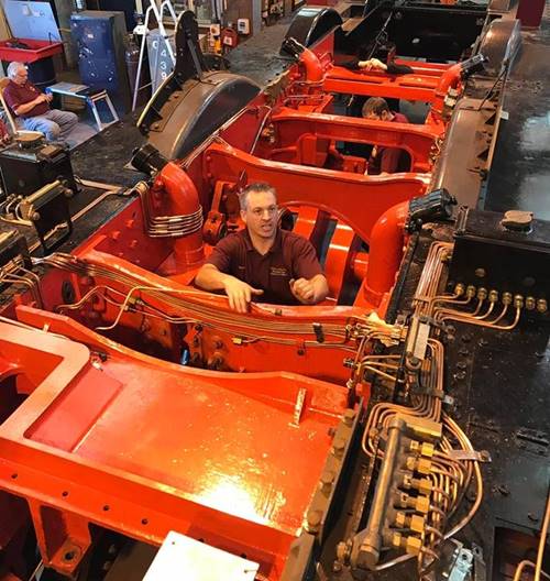
PRCLT engineer Simon Scott inspects 5551 at Crewe. Photo – Andy Collinson
The date arranged was Monday 12th August and a considerable amount of work was required to load all the locomotive parts into either our 4 wheel Vanwide box van or the storage container. Our tools and equipment plus stocks of material and consumables, such as nuts and bolts, all needed to be sorted and packed ready for the move.
It was an early start for the 2-hour drive to be at Crewe for 8am to get the loco shunted out ready for the road transporter. Unfortunately, a technical issue caused a later than planned arrival for the transport team, by which time we had shunted the loco and box van ready for their arrival.
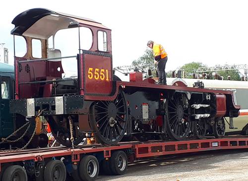
Nigel Day checks over the chassis after loading onto the road trailer at Crewe, 12th August 2019. Photo – Kevin West
With both the loco and box van loaded onto the two trailers departure from Crewe was about 2pm. Due to a weak bridge on the A50 the 60-mile direct journey had to be abandoned for a 92-mile route down the M6 across the top of Birmingham on the M6 toll and back north up the A38.
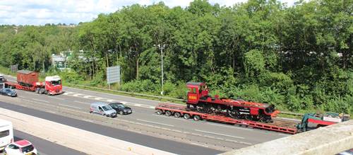
5551 and our Box Van travel down the M6 on their way to Butterley, 12th August 2019. Photo – Oakwood Visuals
Arrival at Butterley station yard was just before 6pm. The first truck with the loco on was then had to be positioned on the unloading track, a ramp built and the loco winched down onto Midland Railway Centre metals at 6.50pm. The ramp was then packed away and the whole process repeated with the second trailer for the box van.
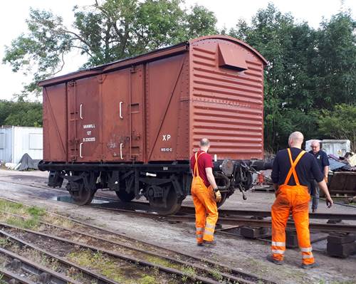
Our Vanwide Box Van is unloaded at Butterley station. 12th August 2019. Photo – Kevin West
By 7.45pm both the loco and van had been shunted out of the yard and onto the main running line into Butterley station ready for the trip to Swanwick Junction and into the West Shed.
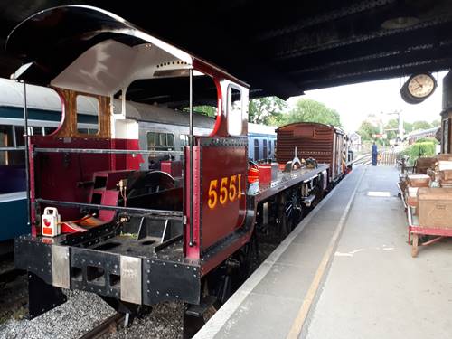
5551 stands in the platform at Butterley station. 12th August 2019. Photo – Kevin West
5551 moves slowly past the former Ais Gill signalbox during the move from Butterley station to the West Shed, 12th August 2019. Photo – Kevin West
The Axleboxes of the loco were filled with oil for the short journey to minimize any damage from dirt ingress. At 8.34pm the loco was finally shunted into the West Shed, it new home and where it will stay until it is finished. We are planning the next time it leaves the shed will be under its own power!
5551 is shunted into the West Shed, 12th August 2019. Photo – Kevin West
For the project team there was just time for a quick wash and then head to the closest pub for dinner before the 2-hour drive home! A long but eventful day.
Andy Collinson celebrates the arrival of 5551 into West Shed, 12th August 2019. Photo – Kevin West
By the end of the week the chassis had been lifted and the Bogie and Leading and Trailing Driving Wheel sets run out. This enabled the accumulated debris to be cleaned from the Bogie and it also to be removed from its wheels for examination of the journals and axleboxes.
The Axleboxes were removed from the Driving axles for the same examination. Fortunately, this examination has shown very little damage to the white metal or axle journals compared to that found on the Centre Wheelset which was removed at Crewe in February.
Axleboxes from 5551’s trailing driving axle following removal at West Shed. Note all associated parts are stored in marked up buckets for safe keeping. Photo – Kevin West
These axleboxes will require replacement of the white metal and a skim of the axle journal to remove the damage incurred due to ingress of debris and lack of lubrication while being shunted at Llangollen.
With the chassis supported on the lifting jacks, the Princess Royal Class Locomotive Trust (PRCLT) engineers, Simon Scott and Nigel Barber then started to undertake a full examination on the chassis in the light of their extensive knowledge of running large express locomotives on the main line. They have come up with a number of questions and suggestions for improvements and changes that we were unaware of or are not covered in the limited original drawings we have.
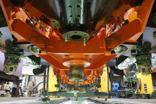
An unusual view of 5551 over the inspection pit. West Shed, August 2019. Photo – Andy Collinson
One area of concern was the fit and sealing of the Rear Cylinder Covers to the Cylinder Blocks. From external examination it appeared that PTFE tape had been used on this joint. This is acceptable on front covers which are regularly removed for access to the Pistons and can be tightened and “pulled up”. The rear covers are mounted solid to the Cylinder Blocks with the Slide Bars attached at the rear, which in turn are attached solidly to the Motion Brackets and Frames. This whole structure is fixed, so it is not possible to re-tighten the Rear Cylinder Covers. The only option was to take down the Slide Bars and remove the Covers to re-make the joint correctly. Once the Covers had been removed it was discovered there was a potential issue with the castings themselves. The shape of the covers is a complicated curved form which is revolved around the centerline of the Cylinder bore. This should be 7/8” (22mm) thick constantly, but it appears that one of the cores had moved in the casting process and the thickness was down to around ½” (12mm) in places. As this would now be a week point in the cylinder structure if we had a hydraulic carry-over of water into the cylinders the only option is to replace the Rear Cylinder Covers with parts to correct specification. The area affected in at the bottom of a pocket almost completely covered by the Slide Bar mountings and was only spotted due to the experience of Nigel Barber’s years of working on locomotives.
This one discovery confirms my belief that our selection of the PRCLT to finish 5551 is the best decision we have made in the last two years. Although to look at the locomotive compared to how it looked at Crewe 12 months ago we now have a more complete understanding of the work involved to get a fully finished and high standard locomotive. To not follow the advice and suggestions made by PRCLT would only put us in a position of having constant breakdowns and mechanical issues out on the line. PRCLT set themselves very high standards, which is the correct way forward for 5551. It is a case of short term pain for long term gain.
On the Bogie the axlebox bearings are lubricated by pouring oil into the under keeps of the boxes. There is no provision to lubricate the axlebox slides, so it has been suggested we fit a small oil pot above each box with pipe feeds to the slides. This has been agreed and approved by our VAB.
The Bogie frame in West Shed 28th August 2019. Photo – Kevin West
At the front of the Bogie is a cross bar which supports the frames. This is shown on the original drawings that the bogie was made to, but when assembled under the locomotive it fouls the Cylinder Relief Valve and Drain Cock fitted to the front of the Inside Cylinder. A modified arrangement of Relief Valve and Drain Cock gear had been designed to clear, but further investigation has shown this to be unsuitable. Following our move to West Shed it has been suggested we install a cranked stretcher similar to those fitted to the BR Standard class 4 tank locomotives, one of which is resident at West Shed. A fabricated Stretcher has been designed and drawings sent to the VAB for approval, which has been granted. Production drawings are now being finalized for manufacture.
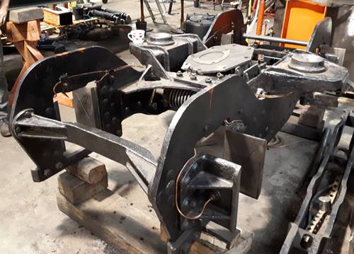
The Bogie frame from BR Class 4 No. 80097 in West Shed showing the shaped stretcher. 28th August 2019. Photo – Kevin West
A full alignment check of the locomotive chassis and Bogie frame will be made and will include full measurement and collation of axlebox gaps, axle centers, and clearance gaps, along with installation of datum studs on the main frame to aid future repair and maintenance. This will also aid the installation of bearings into the motion to ensure we get correct center distances.
The Steam Brake Cylinder had been removed from the Drag Box under the Cab for drilling and fitment of studs to enable final installation.
The Bogie Splashers above the rear Bogie Wheels have had an additional fixing added to the Main Frames and are now much more secure to the Frames.
The six Splashers over the Driving Wheels have never been fully fitted, only just temporarily bolted in position. These are now to be fully positioned and any necessary adjustment made, before they are finally bolted into position.
The Spring Hanger Pins and Brake Hanger Pins are being replaced as we need to add a secondary retention method in place of the original single split pin. This is a recommendation from PRCLT from their main line experience. The Spring Clip fixings will also be changed from the existing bolt to studs and nuts retained by a split pin in line with existing recommendations. The final few fixing bolts in the Running Boards will be fitted at the same time.
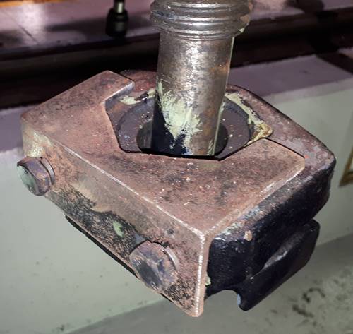
A Driving Axle Spring Clip showing the existing retaining bolts., 28th August 2019. Photo – Kevin West
A new drawhook is being sourced to replace the old part at present used on the front of 5551.
On the lubrication system, PRCLT will finish installation of the system and have suggested some modifications to the clipping of the pipes in line with their main line experience.
An issue with the Lubricator fitted to the LH side has been identified. The unit fitted does not have an oil warmer which is used during the winter to warn the oil and help it flow easily into the cylinder block. We need to investigate the implications of this and make a decision on what to do?
Away from practical work, the Engineering Team, along with other board members, have been spending a huge number of hours working on some very time consuming tasks. These included the the re-work and rectification of work undertaken at Llangollen, which I expect will continue for some time to come before a satisfactory conclusion is reached. These tasks have meant time to undertake design work and drawing creation has been limited, so the output from the design office has been much lower than planned for the last few months.
5551, West Shed. 28th Augustt 2019. Photo – Kevin West
Motion
The Connecting Rods are at Statfold Engineering for replacement of the Big End bearing brasses and white metal, originally fitted at Llangollen which has been found to be of unsatisfactory quality. The Bearings have been pressed out of the rods and a number of issues previously hidden have been found.
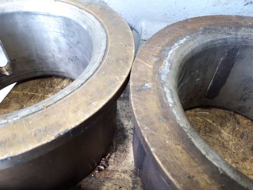
Connecting Rod Big End Bearings following removal at Statfold Engineering, 27th Sept 2019. Photo – Kevin West
Similar work is expected to be required on the Coupling Rods, Radius Rods and Union Links. The Coupling Rod Knuckle Pins which join the Front and Rear Rods are also being replaced as we are unable to obtain any material specifications for the parts previously supplied. Due to the workload at Statfold Engineering we may have the rest of the motion moved back to West Shed before any further work is undertaken. This will allow a complete dimensional check of rod centers to be made in conjunction with the chassis measurement. Quotations for this work to be undertaken elsewhere to a more acceptable time scale have been obtained, but this work will be progressed under the supervision of the PRCLT engineers.
The Valve Crosshead Slides for the Outside Cylinders had suffered surface corrosion whilst in the workshop at Llangollen, and although we had made an attempt to clean these up one of the volunteers at West Shed took it upon himself to polish these parts. We are very grateful.
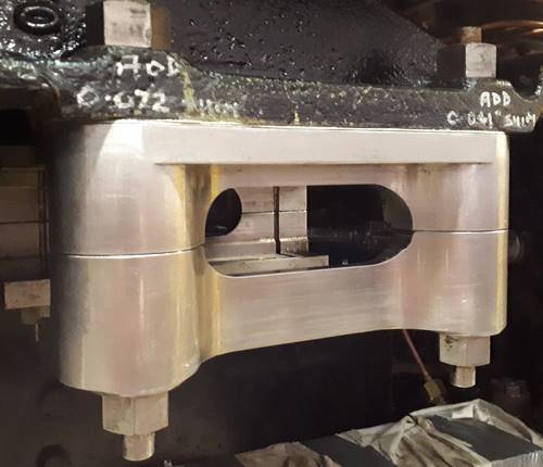
RH Valve Crosshead Guide after cleaning and polishing by PRCLT Volunteers. 28th August 2019. Photo – Kevin West
The Expansion Links have all been removed to finish the installation with the correct end float.
The Driving Wheels are being worked on by the West Shed volunteers to remove the paint from the rims and centre boss to allow presentation of the locomotive with these parts burnished.
Reverser
The Cab Reverser components have all been moved to West Shed including the final piece required, the Reverser Nut. This piece of 12” long cast iron was proving a real difficult piece to machine the female thread to mate up with the leadscrew. The block had been profiled at Harco Engineering some time ago, but progress stalled once they realised they were unable to machine the thread. The block was moved to Statfold Engineering earlier this year for Nick Noon to have a look. We left it with them for a few weeks then called to ask if they would be able to provide a quote to cut the thread. The reply came back, “I didn’t want to give you a quote until I was sure I could cut it! It is almost finished!” So we finally have all the parts ready for assembly, which will be undertaken at West Shed, before being installed in the cab. PRCLT engineers have questioned the strength of the mounting structure, which has been made to the original drawing. A final assessment is required before we make any decisions about possible additions of material to strengthen the mounting.
Crank Pins
Frustration continues!
Following a long period of drawing preparation and submission to the VAB and contractor for approval we finally had an agreed solution to the Crank Pin keyway issue. The Wheelset was delivered back to West Shed in October. The initial inspection revealed a number of mechanical issues and followed by the VAB rejecting the repair method they had previously agreed!
So we are now back to investigating complete replacement of the Crank Pins and a quote has been obtained for this work.
Combination Levers
The order for new Outside Combination Levers has still not been placed as a number of additions to the drawing information is required and has not been completed yet. The contractor who submitted the quotation has recently delivered some components, but the surface quality was not up to standard we expected so we will have to discuss this with the contractor before we place any further orders.
Boiler
Heritage Boiler Steam Services are making good progress on the Boiler assembly.
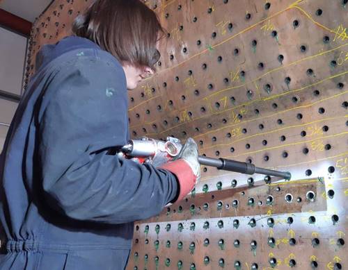
Tapping stay hole in the Inner Firebox. Photo – HBSS
Installation of the firebox stays is almost complete and work is underway in tapping the Outer Firebox plates for the Transverse Stays. These stays run across the Firebox in the space above the top of the Inner Firebox to support the Outer Firebox side plates from the internal pressure.
Internally the steam pipe mounting tray has been manufactured and trial fitted into the barrel.
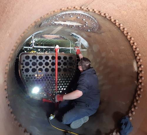
An interior view of the boiler. Photo – HBSS
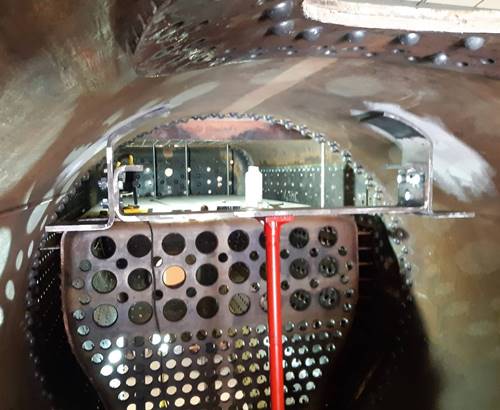
The Boiler Tray is offered up to the inside of the barrel. Photo – HBSS
As mentioned in the last report, we have suffered a setback as the Dome castings have been rejected due to defects in the castings. This came to light after dome castings produced for 5 new boiler under construction for the Isle of Man Railway at the Severn Valley Railway had been rejected due to casting defects. As our dome was supplied by the same foundry we were to we had to have the casting inspected. To do this meant it had to be removed from the boiler barrel, only shortly after it had been riveted in place. Once removed it was sent away for x-ray examination, which showed up similar defects to those found in the IoM boilers. A new process to cover the casting and testing of the IoM domes and ours has been agreed between the foundry and the boiler insurers. The patterns for our are now being manufactured with the castings and testing to follow. It will then need machining before going back to HBSS for fitting onto the barrel. The first of the replacement IoM domes has been made and passed the required testing.
The mounting pad for the Safety Valves needs to be fitted very soon, but we are in need of a reduction in height of the pad to allow the safety valve to sit inside the lower loading gauge. At present we do not know if this can be achieved just within in thickness of the pad, in the height of the safety valve or a combination of the 2? Once again a number of proposals along with covering drawings need to be produced and sent to the boiler insurers for approval before we can get an agreed solution. Once again a lot of work effort for very little visible progress.
We are also investigating the supply of the boiler tubes and Superheater flues. As our boiler uses tubes of a un-standard size we have a minimum material weight we have to order, which equates to just over 300 tubes, slightly over 2 sets (141 required). This means we will have a complete set in stock for when required at the future.
The Superheater Header has been cast finally, following experience gained by the foundry on a smaller header for the Welshpool & Llanfair Railway. This now requires some initial machining to allow a hydraulic test to be carried out.
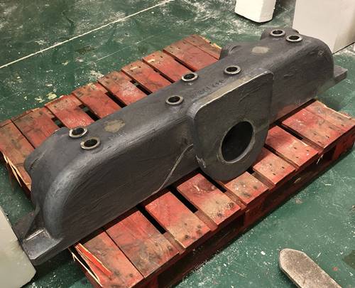
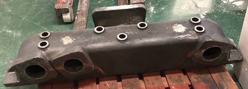
The Superheater Header casting. Photo – Premier Patterns
Ashpan
Following discussions with a number of owners and operators of main line locomotives we have decided to fit a fixed grate to 5551 which closely follows the original drawings we have. There are actually 3 original drawings that show details of the grate, fire bars and carrying brackets, which all differ from each other in minor details. The Carrying Brackets are mounted to long studs fitted into the boiler foundation ring, but the arrangement of studs shown on the boiler drawing does not match the pattern shown on the grate drawings, so a bespoke design will be required.
The ashpan will be fitted with a flush out water system. Plug in hose connections each side will feed a set of internal spray bars to douse and soak the ash before it is raked out of the ashpan. It is also normal ti fit a feed to these strap bars from the injector water feed, so each time an injector is turned on a little water is directed into the ashpan to keep the ash wet.
CAD Design
We have recently been talking to a young engineer involved at the North Yorkshire Moors Railway who is also a CAD Engineer about help us with some of the drawing preparation. This we hope will speed up the production of drawings and enable a number of work streams to be active at any time. He is also conversant with fitment of the electronic systems required for main line running, so we anticipate this to be of great value.
Boiler Fittings
The task of searching out the boiler backhead fittings has been taken on by project volunteer Martin Breakspear. He will be contacting all parties we believe may have information, drawings, patterns or casting that will help us produce the required fittings.
Main Line Running Gear
We now have a package of information relating to the electronic fitment to a LMS class 5 4-6-0. This information needs to be assessed to see how it relates to 5551. We will also be talking to the CAD engineer mentioned above for any assistance he can provide.
Tender Chassis
Work has continued at Leaky Finders on the refurbishment of the Tender chassis. The new Drag Boxes and Frame Spacers between the Inner and Outer Frames to the original riveted design have been riveted into position.
The New Front Drag Box in position in the Frames. 3rd September 2019. Photo – Kevin West
One of the Frame Spacers between the Inner and Outer Frame following riveting into position. 3rd September 2019. Photo – Kevin West
The New Rear Drag Box in position in the Frames. 3rd September 2019. Photos – Kevin West
With the Drag Boxes in position and riveted in place the Buffer Beam could be finally fitted.
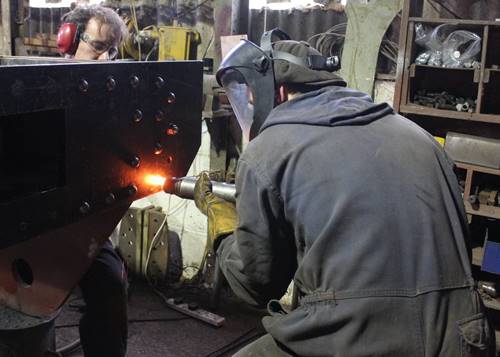
Tender Front Buffer Beam being riveted into position. Photo – Oakwood Visuals
The Horn Guide fitting has been started. A quotation for fitting the axleboxes with bronze liners to restore the correct clearances has been received and the order raised.
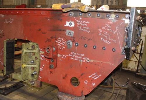
Tender Horn Guides temporarily bolted in position to the Frames. Photo – Oakwood Visuals
A large number of required components have either been manufactured or restored ready for fitting. These include the Brake Pull Rods, Drawbar Pins, Intermediate Buffers, Spring Hanger Brackets and associated Pins.
The Intermediate Buffers. 3rd September 2019. Photo – Kevin West
The parts for the Tender Steps have been delivered to Leaky Finders to replace those lost at Llangollen.
A Step Backplate. Leaky Finders.. 3rd September 2019. Photo – Kevin West
The next major item required will be the Brake Cross Shaft. We have the original part, but it is very worn and suffered severe corrosion during years of service followed by 40 plus years in a scrapyard. A decision need to be made if to repair or replace. Whichever is required new drawings will be required from limited original information.
Tender Tank Design
With the information provided regarding the Main Line Running gear for the class 5 we will be able to finalise the design of the Tender Tank and place the order for the tank manufacture.


